Optical System.Lens & Illumination
OptiWave OptiSystem v21
In an industry where cost-effectiveness and productivity are imperative for success, the award-winning OptiSystem can minimize time requirements and decrease costs related to the design of optical systems, links, and components.
OptiSystem is an innovative, rapidly evolving, and powerful software design tool that enables users to plan, test, and simulate almost every type of optical link in the transmission layer of a broad spectrum of optical networks from LAN, SAN, MAN to ultra-long-haul. It offers transmission layer optical communication system design and planning from component to system level and visually presents analysis and scenarios.
SPECIFIC BENEFITS
Provides global insight into system performance
Assesses parameter sensitivities aiding design tolerance specifications
Visually presents design options and scenarios to prospective customers
Delivers straightforward access to extensive sets of system characterization data
Provides automatic parameter sweep and optimization
Integrates with the family of Optiwave products
APPLICATIONS
Created to address the needs of research scientists, optical telecom engineers, system integrators, students, and a wide variety of other users, OptiSystem satisfies the demand of the evolving photonics market for a powerful yet easy-to-use optical system design tool.
OptiSystem enables users to plan, test, and simulate (in both the time and frequency domain):
Optical network designs including OTDM, SONET/ SDH rings, CWDM, DWDM, PON, Cable, OCDMA
Single-mode/multi-mode transmission
Free space optics (FSO), Radio over fiber (ROF), OFDM (direct, coherent)
Amplifiers and lasers (EDFA, SOA, Raman, Hybrid, GFF optimization, Fiber Lasers)
Signal processing (Electrical, Digital, All-Optical)
Transmitter and receiver (direct/coherent) sub-system design
Modulation formats (RZ, NRZ, CSRZ, DB, DPSK, QPSK, DP-QPSK, PM-QPSK, QAM-16, QAM-64)
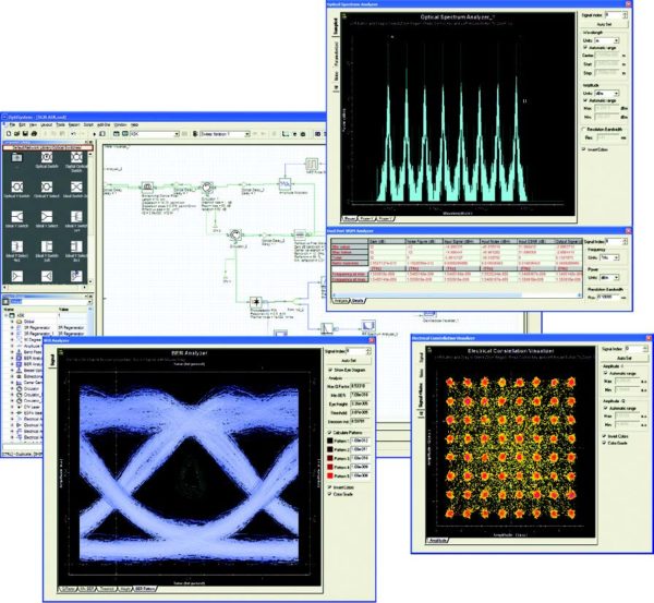
System performance analysis (Eye Diagram/ Q-factor/BER, Signal power/OSNR, Polarization states, Constellation diagrams, Linear and non-linear penalties)
Component Library
The OptiSystem Component Library includes hundreds of components that enable you to enter parameters that can be measured from real
devices. It integrates with test and measurement equipment from different vendors. Users can incorporate new components based on
subsystems and user-defined libraries or utilize co-simulation with a third-party tool such as MATLAB or SPICE.
Integration with Optiwave Software Tools
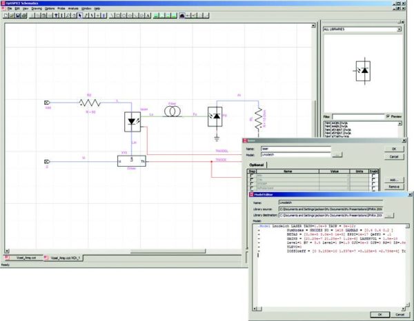
OptiSystem allows you to employ specific Optiwave software tools for integrated and fiber optics at the component and circuit level: OptiSPICE, OptiBPM, OptiGrating, and OptiFiber.
Mixed signal representation
OptiSystem handles mixed signal formats for optical and electrical signals in the Component Library. OptiSystem calculates the signals using the appropriate algorithms related to the required simulation accuracy and efficiency.
Quality and performance algorithms
In order to predict the system performance, OptiSystem calculates parameters such as BER and Q-Factor using numerical analysis or semi-analytical techniques for systems limited by inter-symbol interference and noise.
Advanced visualization tools
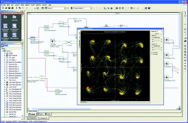
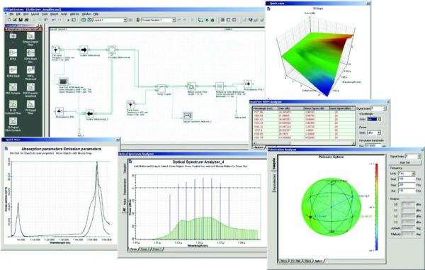
Advanced visualization tools produce OSA Spectra, signal chirp, eye diagrams, polarization state, constellation diagrams, and much more. Also included are WDM analysis tools listing signal power, gain, noise figure, and OSNR per channel.
Data monitors
You can select component ports to save the data and attach monitors after the simulation ends. This allows you to process data after the simulation without recalculating. You can attach an arbitrary number of visualizers to the monitor at the same port.
Hierarchical simulation with subsystems
To make a simulation tool flexible and efficient, it is essential to provide models at different abstraction levels, including the system, subsystem, and component levels. OptiSystem features a truly hierarchical definition of components and systems, allowing the simulation to be as detailed as the desired accuracy dictates.
Powerful Script language
Using standard VB Script language, you can enter arithmetical expressions for parameters and create global parameters that can be shared between components and subsystems. The script language can also manipulate and control OptiSystem, including calculations, layout creation, and post-processing.
State-of-the-art calculation data-flow
The Calculation Scheduler controls the simulation by determining the order of execution of component modules according to the selected data flow model. The main data flow model that addresses the simulation of the transmission layer is the Component Iteration Data Flow (CIDF). The CIDF domain uses run-time scheduling, supporting conditions, data-dependent iteration, and true recursion. OptiSystem Optical Communication System and Amplifier Design Software
Report page
A fully customizable report page allows you to display any set of parameters and results available in the design. The produced reports are organized into resizable and moveable spreadsheets, text, 2D and 3D graphs. It also includes HTML export and templates with pre-formatted report layouts.
Bill of materials
OptiSystem provides a cost analysis table of the system being designed, arranged by system, layout, or component. Cost data can be exported to other applications or spreadsheets.
Multiple layouts
You can create many designs using the same project file, which allows you to create and modify your designs quickly and efficiently. Each OptiSystem project file can contain many design versions. Design versions are calculated and modified independently, but calculation results can be combined across different versions, allowing for comparison of the designs.
FEATURES
OptiSystem provides the most comprehensive optical communication and photonics design suite for optical design engineers. Its key features include:
Transmitters library
OptiSystem’s Transmitters library contains an extensive selection of optical sources (Fabry-Perot, DFB, VCSEL), electrical and optical signal pulse
generators, optical modulators (EA, MZ), electrical modulators and coders (QAM, PAM, FSK, OFDM), and multi-mode signal generators (Laguerre-Gaussian, Hermite-Gaussian).
Designers can choose between advanced physical-based or measurement-based (empirical) models for modeling the static and dynamic behavior of semiconductor lasers. Our physical-based models include 1D and 2D multi-mode laser rate equations, allowing designers to switch between bulk laser rate models and the transmission line matrix method (TLMM).
Receivers library
The Receivers library contains all the building blocks needed to model optical communication receiver sub-systems accurately. Components include regenerators (clock/data recovery, 3R), electronic equalizers, threshold detectors, decision circuits for PSK/QAM modulation, PIN and APD photo-detectors, demodulators (OFDM, frequency, phase-amplitude), decoders (PAM, QAM, PSK, etc.), and digital signal processing (DSP) toolsets for single and dual polarization coherent PSK and QAM systems.
Optical fibers
Advanced, highly parameterized optical fiber models can be used to characterize single-mode and multi-mode signal propagation, including linear (dispersion), stochastic (PMD), and non-linear impairments (FWM, self-phase modulation, and cross-phase modulation). Using OptiSystem’s Bidirectional optical fiber component, it is possible to model and measure Rayleigh, Brillouin, and Raman scattering effects.
Amplifiers
A comprehensive suite of steady state and dynamic optical amplifier models is provided, including advanced doped fiber models (Er, Er multi-mode, Er-Yb, Yb, Yb multi-mode, Tm, Pr) for detailed physical fiber amplifier design; EDFA and EDFA black box (gain spectrum, noise figure measurements) for WDM network systems design; dynamic and average power Raman models; and 1D/2D semiconductor optical amplifier models (lumped rate equation, traveling wave, TLMM). Electrical domain amplifiers are also provided for receiver design (transimpedance, automatic gain control, and limiting amplifier applications).
Network design tools
Network design tools include ideal and non-ideal models for optical switches, multiplexers, de-multiplexers, array waveguides (AWGs), fiber connectors, and PMD emulators.
Filters
A variety of electrical and optical filters are provided for sub-system and system design simulation, including standard filter functions (Bessel, Gaussian, RC, Raised Cosine, etc.), digital IIR/FIR filters, periodic filters, reflective/FBG filters, measured filters, S-parameters filter, and acousto-optic.
Passives
An extensive selection of optical and electrical passive components can be used to build a variety of component and sub-system designs. Optical devices include attenuators, couplers, splitters and combiners, polarization controllers, reflectors, taps, isolators, and circulators. Electrical devices include 180 and 90-degree hybrid couplers, DC blockers, power splitters and combiners, and RF transmission lines.
Models are also provided to allow designers to use measured data to characterize device transfer functions, including small signal scattering (S) matrices and the Jones matrix.
Signal processing
Signal processing tools are provided for manipulating optical, electrical, and binary signals. Functions and operations include bias generators, gain, signal addition and subtraction, normalizers, electrical differentiators and integrators, down-samplers, serial-parallel and parallel-serial converters, electrical flip flops, and electrical/binary logic operators.
Spatial and free space optics design tools
OptiSystem has specialized components that can model free space optical channels (antenna characteristics, atmospheric propagation) and the spatial analysis of multi-mode signal coupling between devices (multi-mode generators, spatial connectors, thin lenses, spatial visualizers).
Visualization tools
Visualization and post-simulation analysis tools include BER test sets and analyzers, eye diagram analyzers, spectrum analyzers, oscilloscopes, optical time domain viewers, power meters, polarization analyzers, spatial visualizers, encircled flux, DMD analyzer, photonic all parameter analyzer, filter analyzer, and S-parameter extractor.
Related articles
- Lighttools v9.1 free download
- RSOFT Photonics CAD Suite 2024
- Lighttools v2025.03(Illumination Design)
- CODE V v2025.03(Optical.Lens Design)
- Lucidshape v2024.09(Best-in-Class Optical Design for Automotive Engineers)
- Lumerical 2025 R1.0.3(FDTD,Charge,Interconnect,Device,etc...)
- SPEOS v2025 R1.03
- Zemax OpticStudio 2025 R1.03
- VPIphotonics Design Suite v11.5
- Operant Peak Spectroscopy 4.00.494
Comment/コメント
Comment list/コメントリスト
- No comments/コメントはありません


